Socket Weld Flange (SWRF)
Technical Diagram: Socket Weld (SW) Profile
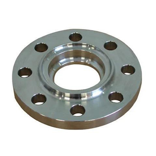
Socket Weld flanges are primarily used on smaller sizes of high-pressure pipes. The pipe is inserted into a "socket" or recessed area and fillet welded around the top. This provides a smoother bore and better flow characteristics than a threaded flange.
Key Features and Standards
- Bore Design: Features a counterbore to match the pipe's ID.
- Size Range: Typically NPS 1/2" to NPS 3".
- Standards: ASME B16.5, BS 3293.
- Pressure classes: 150, 300, 600, 1500.
Dimensional Chart — ASME B16.5 Class 150 (mm)
Standard dimensions in millimeters for Class 150 Socket Weld Flanges.
| NPS (Inch) | Outside Dia (O) | Socket Dia (B) | Socket Depth (D) | Hub Dia (X) | Bolt Circle (W) | Bolt Holes (Qty) |
|---|---|---|---|---|---|---|
| 1/2" | 90 | 22.2 | 10 | 30 | 60.3 | 4 |
| 3/4" | 100 | 27.7 | 11 | 38 | 69.9 | 4 |
| 1" | 110 | 34.5 | 13 | 49 | 79.4 | 4 |
| 1-1/4" | 115 | 43.2 | 14 | 59 | 88.9 | 4 |
| 1-1/2" | 125 | 49.1 | 16 | 65 | 98.4 | 4 |
| 2" | 150 | 61.1 | 17 | 78 | 120.7 | 4 |
| 2-1/2" | 180 | 74.2 | 19 | 90 | 139.7 | 4 |
| 3" | 190 | 90.2 | 21 | 108 | 152.4 | 4 |
Materials available
- Carbon steel: ASTM A105 (Standard forging).
- Stainless steel: ASTM A182 F304/304L, F316/316L.
- Alloy steel: ASTM A182 F5, F11, F22.
Installation Note: A gap of approximately 1.5mm should be maintained between the pipe end and the socket bottom to allow for thermal expansion.